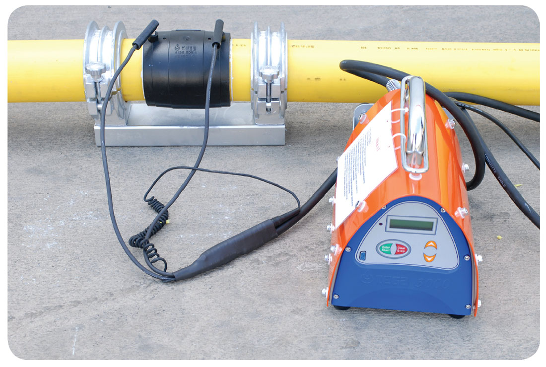
20 < d ≤ 355
IMPORTANT NOTES
– Below instructions should be followed absolutely step by step.
– We recommend using pipes with limited dimension tolerance range.
– The fusible pipe series are shown in the SDR labeling on coupler.
– Installation technician must be trained and certified to install Tega large diameter couplers.
– Fusion with other pipe materials such as PP, PVC etc. is not possible.
– Installation can be done at ambient temperatures between -5 °C and +45 °C. If ambient temperature is not within these
limits use of welding tent is required.
– For general safety reasons, keep a distance of min. 1 m to the fusion site during fusion process.
– Make sure equipment that requires calibration is calibrated
– Fitting should be inspected for damage before installing
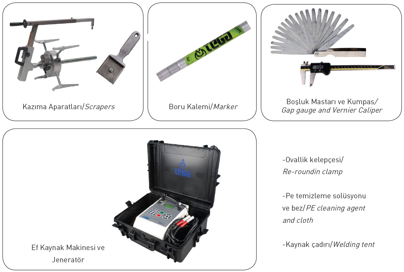
1. Pipe Cutting:
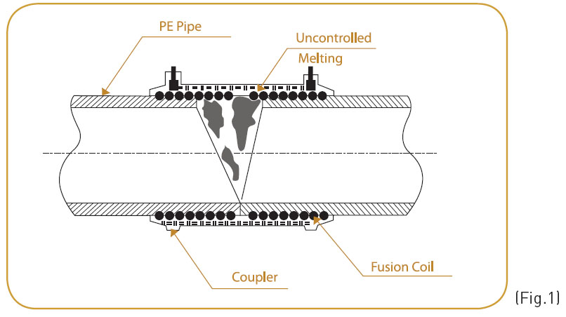
For the pipe cutting, a suitable cutter for plastics must be used. The pipes are to be cut square with this cutting tool. If the pipe is not cut at right angles, this results in contact between heating coils and the pipe, which causes uncontrolled flow of molten due to overheating. (Fig. 1)
2. Marking and scrapping of the fusion zone:
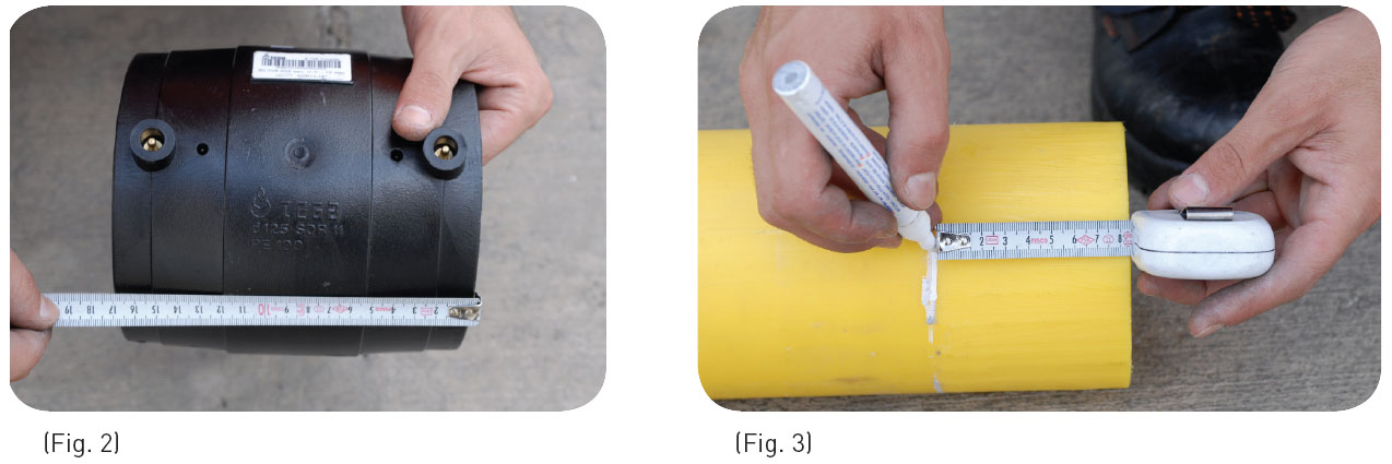
Fusion zone which is the insertion depth of fitting, must be marked with a marker on the pipe end or on the spigot end.
Measure the total length of coupler and calculate the half length. (Fig. 2) Mark the measured length on pipe surface with a marker (Fig.3)
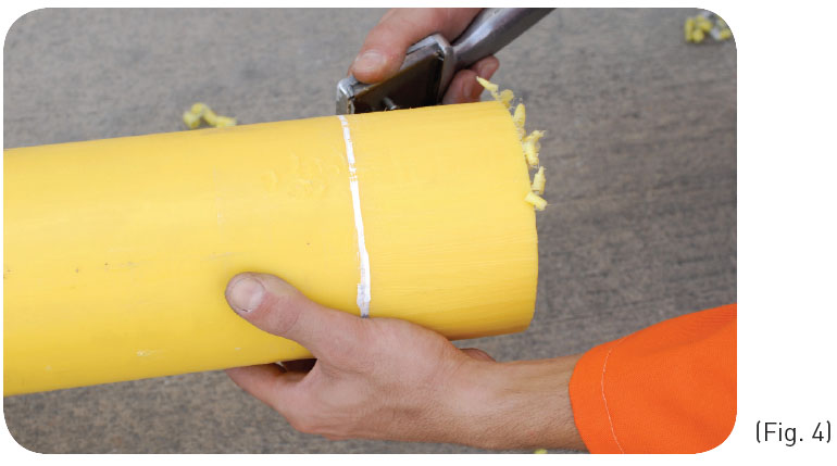
In order to remove the oxide layer of the pipe, scrape carefully the fusion zone using a scraper. (Fig. 4)
In order to remove the oxide layer completely, the pipe must be scraped so that shavings are formed and marking line is removed. This operation ensures removal of oxide layer, which may cause unsuitability for the jointing.
The prepared surface must be protected against unfavorable weather conditions.
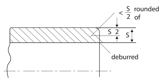
After that, the internal edge must be deburred and the outer edge rounded off as illustrated in fig. 4
3. Getting Rid of Ovalization
The ovality of the pipes in the fusion zone mustn’t be more than 1.5 % of the outer diameter of the pipe. If necessary, rerounding clamps must be used.
4. Degreasing of the Fusion Zone:
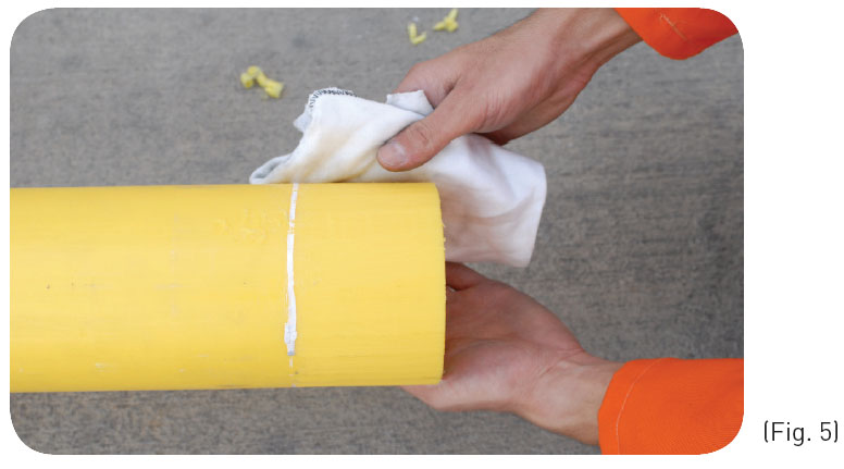
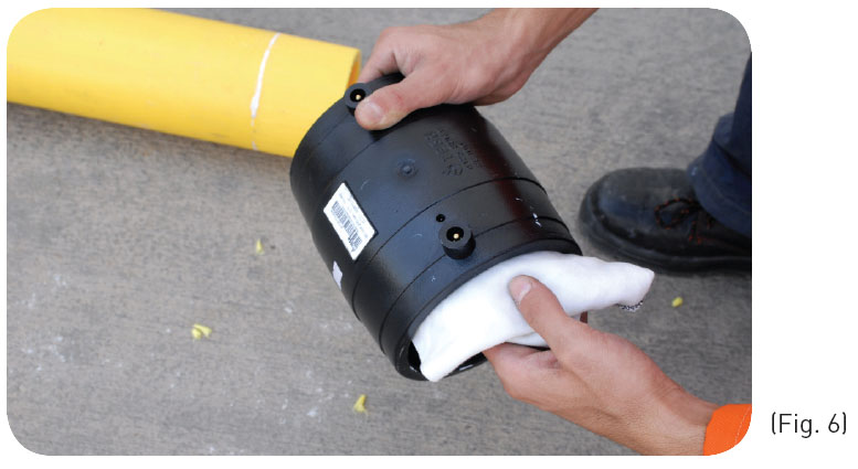
Remove fitting from its package without touching the fusion zone. Make a visual check to ensure fiting is undamaged. The prepared end or spigot end and internal face of coupler must be degreased with a suitable cleaning agent and a white absorbent and nonfibrous cloth. (Fig. 5-6)
As a cleaning agent; isopropyl alcohol can be used (The alcohol content mustn’t be less than 96% by volume).
Degreased surfaces must be protected against dirt or unfavorable weather conditions.
5. Inserting of the pipe end or spigot end into the coupler:
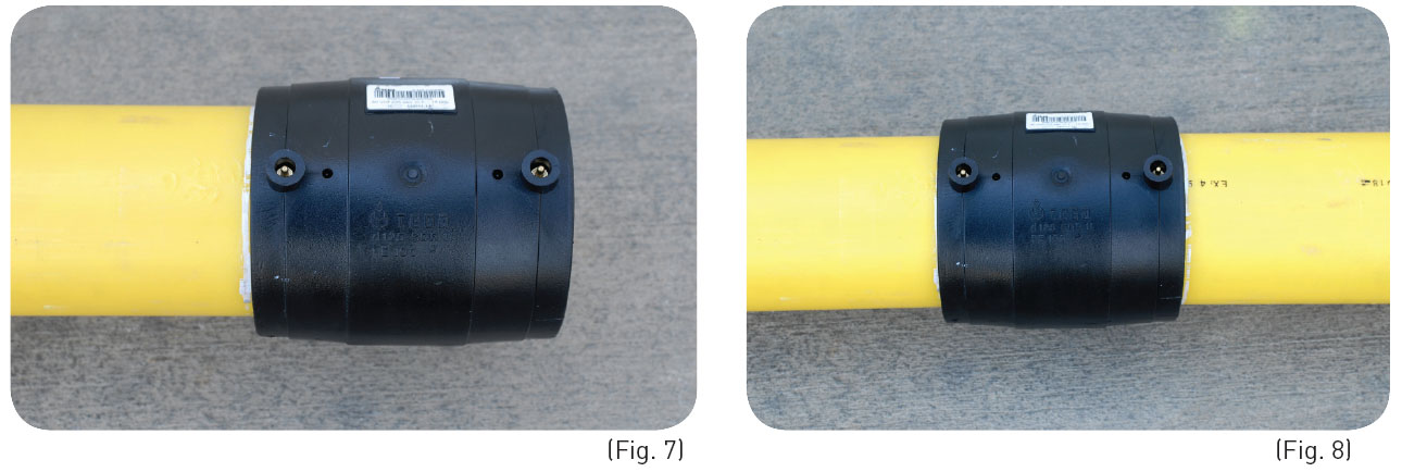
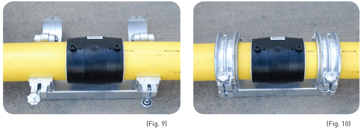
Inserting of the pipe end or spigot end into the coupler must be done without causing any tilting with respect to each other’s (Fig. 7-8-9-10)
The contact terminals of the coupler must be easily accessible.
In order to get of bending stresses, be sure that couplers can be turned easily and do not let the pipes to support their own weight in the fitting.
In inserting operation, it must be ensured that pipe end or spigot end contacts with the stoppers of the coupler.
6. Fusion:
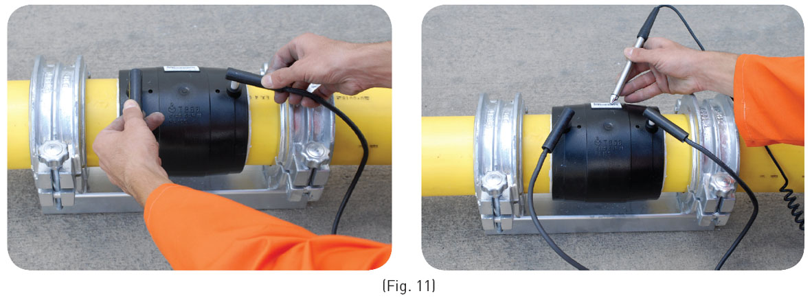
Provided that the information given in the operating instructions are followed step by step and there is no problem, the fusion process can be started after data of the coupler is set to the fusion control unit by manually or by means of bar-code reader. (Fig. 11)
Use only universal Fusion Control Unit.
During Fusion operation, fusion indicators which shows the completion of process must be observed. There may be less or more melt in the indicators. This is because of the gap formed between the coupler and pipe end or spigot end.
As a safety precaution, be careful to stay at least 1 m away from the fusion area.
If the fusion process is interrupted for any reason (e.g. due to power failure) the fusion process can be repeated after the joint cooled adequately. Find these cooling times on TEGA Couplers’ barcode labels.

